Advanced Generator Modeling and Validation for Emerging AI Load Profiles
 Print
PrintAUTHOR
Majid Adeli
Staff Engineer - Advanced Dev., Software Systems
INTRODUCTION
AI data centers introduce highly synchronized and dynamic load behavior that can create rapid power swings, ramp-rate challenges, and low-frequency oscillations. These characteristics require generator performance to be evaluated beyond steady-state capacity, with focus on voltage stability, frequency response, transient recovery, and utility compatibility.
This paper reviews emerging AI load dynamics and presents Rehlko’s approaches for addressing them through high-fidelity generator modeling, reduced order simulation, and test-cell validation under AI data center load profiles. The developed models apply IEEE-based generator modeling, Standstill Frequency Response (SSFR) parameter identification, excitation/ governor modeling, and Reduced-order Modeling (RoM) to evaluate and predict genset voltage, frequency, damping, recovery, and stability under fast AI load changes. These modeling approaches enable accurate and efficient evaluation of utility requirements, hardware needs, and genset dynamic response, helping optimize system sizing for AI data center load profiles.
Experimental validation across hundreds of load-step cases shows strong agreement between measured and simulated transient behavior, providing confidence that Rehlko generators can support today’s and future AI data center load requirements.
LOAD TRANSIENT AND UTILITY REQUIREMENTS
Traditional cloud data center loads consist of many independent applications and users operating at different times, resulting in statistically diverse demand patterns. In contrast, large AI training jobs can synchronize thousands of nodes around the same phase of execution. This makes the aggregate load less random and more coherent. Modern AI training data center loads can be large, synchronized, periodic, and rich in low-frequency oscillatory content. The authors in [1] explain that frontier AI training jobs can span tens of thousands to more than one hundred thousand GPUs, with many GPUs operating in lockstep under a bulk-synchronous training model. During each training iteration, GPUs alternate between compute-intensive work and communication/synchronization phases, causing large swings in electrical demand. Accordingly, the workload has two dominant phases:
COMPUTE PHASE
GPUs execute local mathematical operations, such as matrix multiplications, and may operate close to their Thermal Design Power (TDP).
COMMUNICATION PHASE
GPUs synchronize model updates, often through collective operations such as all-reduce, and their power draw may fall much closer to idle levels. See Figure 1.
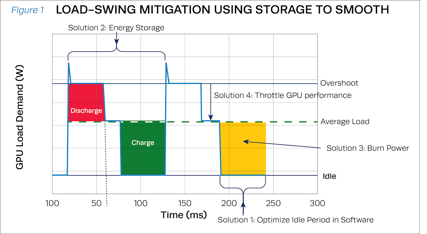
Because these phases occur repeatedly and synchronously across a very large number of GPUs, the resulting electrical load is highly dynamic. At the data center level, many racks participating in the same training job can create facility-scale power oscillations.
Utilities may impose requirements on magnitude, ramp rate, and frequency-domain emissions to avoid aligning data center power swings with sensitive grid or generator dynamics that could increase electrical stress, voltage flicker, subsynchronous interactions, or instability risk; therefore, stabilizing AI training loads requires both adequate energy-For load swings below 1 Hz, resonance is mainly tied to the natural dynamics of long transmission lines that can oscillate independently. In the 1–2.5 Hz band, oscillations can occur between closely coupled sources (for example, units within the same plant or nearby plants). At ~7 Hz to >100 Hz, the key risk is shaft torsional resonance in a turbine-generator: the connected rotating sections can twist back and forth against each other because the long shaft segments act like springs. If a periodic disturbance lines up with one of these torsional critical frequencies, the twist oscillations can amplify, sending alternating torque through the final shaft link into the generator, and raising mechanical stress even when the original disturbance is small.
Utility providers may require frequency-domain limits, in addition to ramp-rate limits, with interconnection requirements that set oscillation attenuation and amplitude/frequency thresholds, supported by high-resolution monitoring, to prevent large periodic loads from exciting resonant, inter-area, or sub synchronous grid modes., [2]. In practice, this type of requirement defines a critical frequency band (for example, 0.1–20 Hz) and sets a quantitative limit on how much oscillatory content the load is allowed to inject within that band (for example, a cap such as no more than 20% of the total spectral/harmonic energy). The intent is to reduce the risk of subsynchronous resonance, voltage flicker, and equipment stress, especially because measured AI load spectra can cluster around 0.2–3 Hz and may shift over time as workload behavior evolves, so the specification must cover a dynamic range rather than a single fixed frequency.
For synchronized AI training loads in [1], mitigation is layered: (1) software reduces or reshapes idle/compute behavior to minimize swing severity, and (2) hardware uses energy storage as a low-pass filter for fast load swings while GPU power smoothing/burn power and/or performance throttling approaches act as backstops for corner cases, as shown in Figure 1, [3]..
UTILITY REQUIREMENTS
GRID
Utilities and grid operators increasingly expect large AI facilities to behave as predictable, controllable loads so that rapid, synchronized GPU-driven step changes do not cause voltage/ frequency deviations or violate interconnection limits. Accordingly, [3] frames the compliance objective as meeting utility requirements for ramp-rate control, transient stability, harmonics/ flicker, and voltage ride-through, enabled through coordinated controls spanning compute settings, facility power conditioning, and real-time power support.
BESS
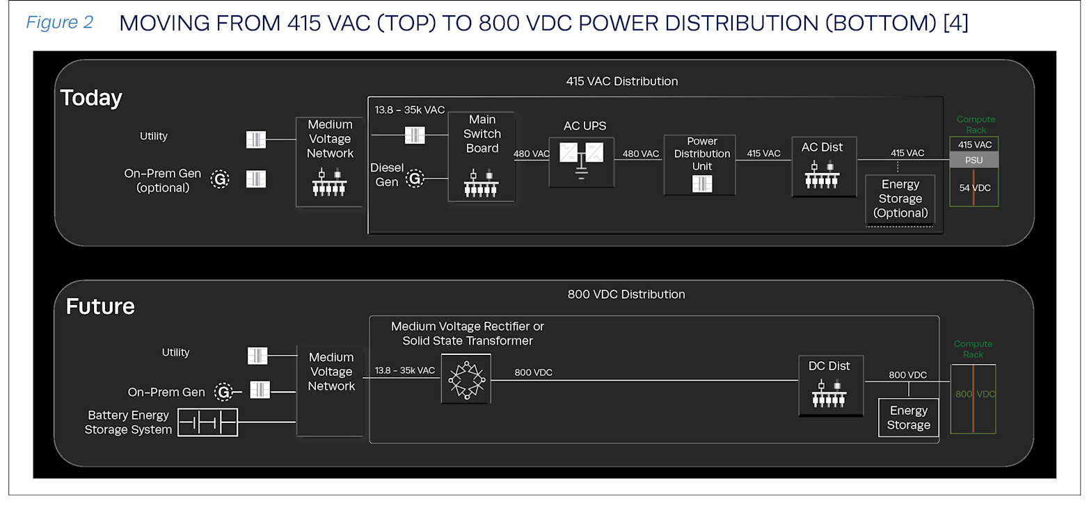
To satisfy these requirements, NVIDIA [3] emphasizes a dual-layer energy-storage strategy: a facility-side Battery Energy Storage System (BESS) located near the utility interconnection and any on-site generation to provide load averaging, grid-forming support, and transitional power during utility-to-generator transfers, complemented by near-rack short-duration storage (e.g., capacitors) that suppresses sub-millisecond AI transients (down to ~400 μs), limits effective ramp rates, and stabilizes the delivered 800 VDC rail for sensitive compute equipment, as shown in Figure 2.
GRID - RACK PATH
Power flows from the Medium Voltage (MV) (13.8 – 35 kVAC) step down into LV switchboards, then through AC UPS to provide immediate ride-through power during sags/short outages, PDUs, and AC distribution to deliver 415 VAC to each compute rack.
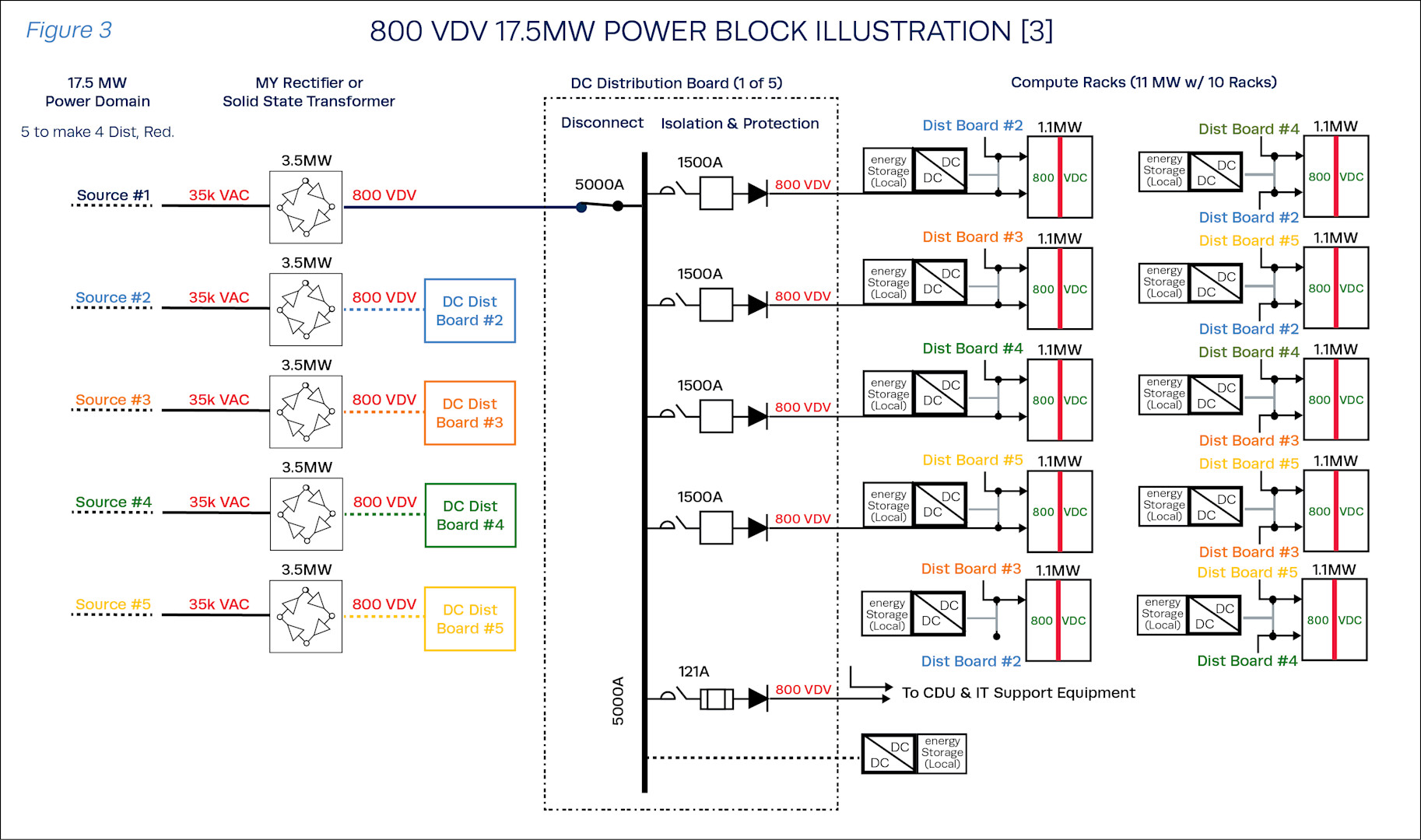
In the state-of-the art 800 VDC architecture [3], [5], the facility converts MV AC directly to an 800 VDC distribution bus using MV rectifiers or solid-state transformers, overcoming rack power density and volatility increase due to AI workloads and eliminating much of the traditional low-voltage AC layering and reducing conversion stages and distribution losses. Figure 3 shows, this architecture is implemented as a 17.5 MW power block built from five 3.5 MW MV rectifiers, one of which is a spare, where each rectifier converts 35 kVAC to 800 VDC and feeds a centralized 5000 A DC distribution board, which then distributes power via 1500 A feeders (bus ducts or liquid-cooled cables) equipped with isolation and protection elements to supply the compute racks and supporting equipment.
GENSET MODELING
Next, we discuss the available approaches for modeling each element of the data center generator system, including the synchronous generator, AVR/exciter, engine, and governor.
Accurate modeling and simulation are essential to verify reliable utility-connected genset operation during normal grid-parallel operation and major transients, including AI workload ramps, utility disturbances, load transfers, and backup-power transitions. This is particularly important for AI datacenters, where synchronized GPU workloads can impose rapid facility-level load swings and challenge grid interconnection limits. Accordingly, the next sections review the available modeling approaches for each major genset subsystem, including the engine/governor, excitation system, and synchronous generator, followed by a discussion of the proposed modeling approach.
ENGINE / GOVERNOR MODELING
SIMPLE ENGINE-GOVERNOR
The simple engine–governor model lumps the diesel engine, speed regulator, and actuator into a compact transfer-function-style structure, using PI speed control and an engine delay to set fuel and mechanical power. It’s fast and easy to tune with limited data, but it misses key dynamics, so it often fails to match frequency transients, especially during the rebound period, compared with higher-fidelity models like GGOV1D.
WOODWARD DEGOV (TRADITIONAL DIESEL GOVERNOR MODEL)
The Woodward DEGOV model is a widely used, industry-standard diesel governor representation for transient studies, with a more detailed actuator dynamic structure (multiple time constants) and an engine delay. It is popular because it is well recognized and generally more realistic than simple governor models. It can be parameter-heavy, which makes tuning difficult without good transient data.
IEEE GGOV1
This model is a widely recognized IEEE turbine/engine governor framework, commonly used for gas turbines. For their standalone isochronous diesel case, they retain only the speed control loop and omit temperature, acceleration, and load-control modes. It offers a richer control structure than simple/DEGOV in its full form (e.g., valve/fuel-flow concepts) and can be configured for isochronous or droop operation, and it fits P and Q overshoot better than the simpler models. However, the standard GGOV1 uses a first-order actuator, which is insufficient to capture rebound-period frequency transients, and it requires careful diesel-specific adaptation such as estimating engine gain and no-load fuel flow from fuel-flow vs. power data.
GGOV1D
The proposed GGOV1D model is built on IEEE GGOV1 but replaces the standard first-order actuator with a third-order actuator transfer function (added poles plus a zero) to better reproduce the measured diesel generator frequency response. This higher-order actuator provides additional tuning freedom: additional poles shape rise time and damping while the zero helps match overshoot and settling behavior, allowing the model to capture the arresting (nadir) and rebound frequency dynamics more accurately than the simple, DEGOV, or GGOV1 variants. It also incorporates diesel-relevant quantities such as engine gain (from fuel-flow vs. power) and no-load fuel flow in per-unit. The main tradeoff is increased parameter count and tuning complexity. It is best suited when high-fidelity frequency transients are needed for microgrid control design, especially for coordinating diesel Primary Frequency Response (PFR) with inverter-based Fast Frequency Response (FFR) to cover the fast initial transient.
ALTERNATOR MODELING
The excitation system supplies DC field current to the synchronous generator rotor, thereby controlling the generator’s terminal voltage and reactive power during disturbances and load changes. Exciter/AVR modeling for a Genset is typically chosen from the IEEE 421.5 family of reduced-order excitation system models (commonly grouped as DC-type, AC/brushless-type, and static-type exciters), each involving a tradeoff between fidelity and simplicity. IEEE treats the AVR as one subsystem inside the complete excitation system.
DC-type models (e.g., DC4B) are a good match when the hardware behaves like a field controlled DC commutator exciter with a continuously acting terminal-voltage regulator, offering realistic voltage/reactive-power transients but requiring careful tuning and respecting model constraints; AC/brushless models better represent brushless exciters (AC exciter + rotating rectifier) and can capture their characteristic lags/limits but may need more parameters and test data; and static exciter models represent static AVR/rectifier-based field supply (often PMG-fed) and are widely applicable and responsive, though they can still be parameter sensitive and may omit vendor-specific inner loops because IEEE 421.5 models are intentionally reduced order.
Given these IEEE 421.5 excitation system model approaches, an additional V/Hz limiting block is often needed when over-fluxing protection must be represented, because IEEE 421.5 does not provide a standardized V/Hz limiter model.
MACHINE MODELING
CONSTANT-VOLTAGE-BEHIND-REACTANCE (CLASSICAL THEVENIN)
The simplest generator model represents the machine as a constant internal voltage behind a single reactance (typically transient reactance for first-swing studies), neglecting saliency (direction dependency of magnetic behavior of salient-pole rotors) and holding the internal voltage magnitude constant over the short transient. It is fast and needs minimal data, but it cannot capture exciter/AVR effects or detailed rotor (damper) dynamics, so it may miss important voltage/reactive and damping behavior.
D-Q AXIS EQUIVALENT-CIRCUIT MODELS-INCREASING ROTOR DETAIL (MODEL 1.x,2.x AND 3.x)
IEEE Std 1110 [6] Figure 4 organizes synchronous-generator models as direct-axis and quadrature-axis equivalent circuits whose “order” increases with the number of equivalent damper/rotor circuits represented on each axis (e.g., Model 2.1, 2.2, up to Model 3.3), enabling progressively more accurate representation of damper currents, rotor body effects, and field dynamics.
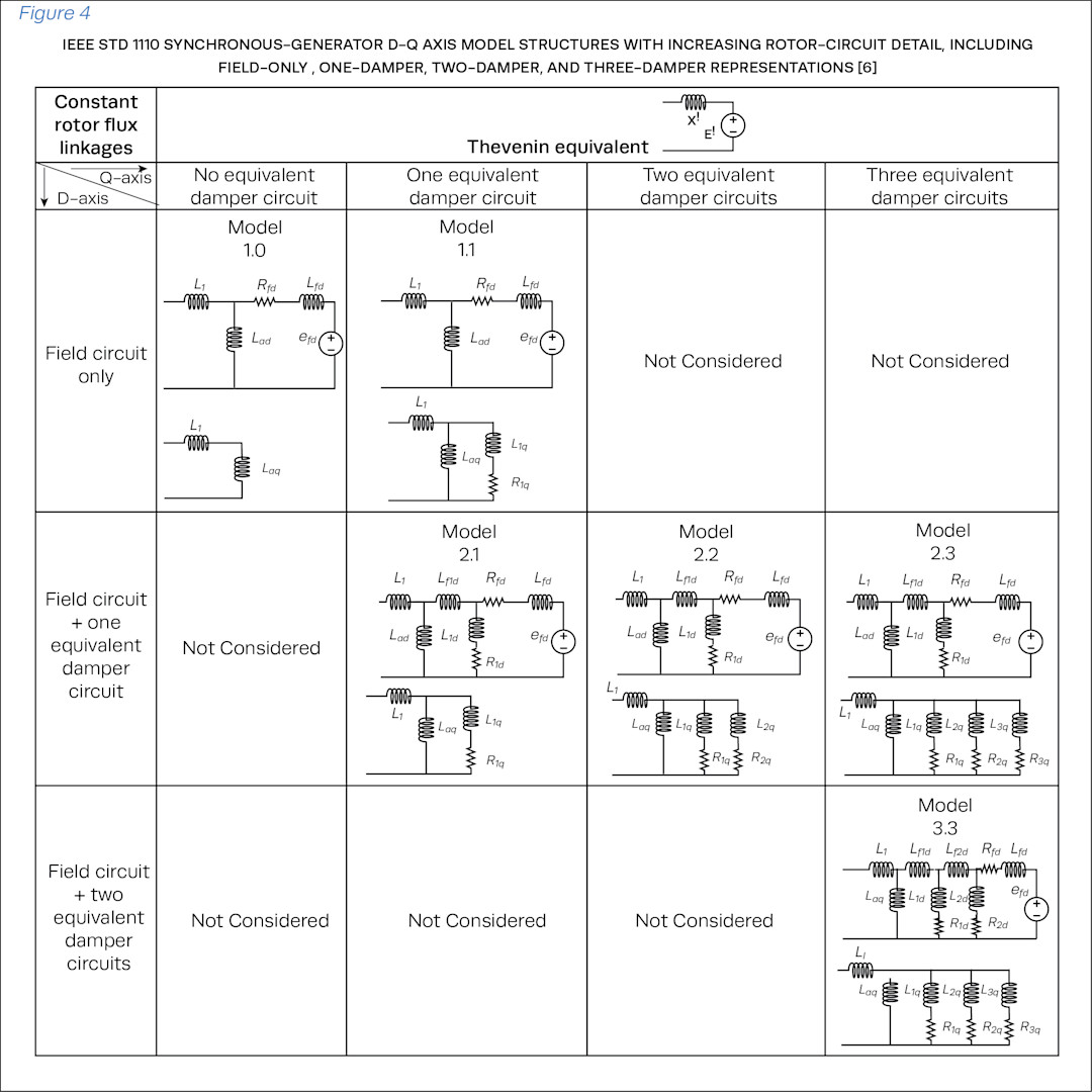
The key benefit is greater physical realism in transient and small-signal studies because these models better capture electromagnetic damping, sub-transient behavior, and field-circuit influence, which IEEE 1110 notes can be essential and can be masked by oversimplified models. The tradeoff is parameter complexity and identifiability: higher-order models require more test data, manufacturer data, or FEA data, and some equivalent-circuit parameters are not uniquely determined from terminal measurements alone, increasing calibration effort.
IEEE 115 [7] offers two main ways to get the parameters needed for IEEE 1110 generator models (reactances/ time constants or equivalent d–q model parameters): (1) conventional time-domain tests (sudden short-circuit–based methods) are well-proven and directly reflect real transient behavior, but can be risky and logistically heavy for older/large machines; (2) Standstill Frequency Response (SSFR) test which at standstill estimates the same model parameters from frequency-response data and can produce both d- and q-axis models with lower operational risk, but requires careful low-frequency measurement, temperature correction, and rotor positioning. SSFR can support high-order fitting and provide frequency-domain data from which we estimate operational quantities (e.g., Ld(s), Lq(s) and translate them into an equivalent-circuit parameter set for the chosen IEEE-1110 model, enabling calibration beyond nameplate/manufacturer data alone.
It is important to note that, in this workflow, the SSFR test is treated as a stepped-frequency steady-state measurement: at each injected frequency, the sinusoidal response is allowed to reach steady state and is then averaged/integrated over a specified number of cycles before the magnitude and phase are extracted. This is important because the resulting transfer functions represent the machine’s linearized frequency response at each operating point, rather than transient behavior during a continuous frequency sweep.
FINITE-ELEMENT ANALYSIS (FEA)
FEA time-step coupled models solve the underlying field equations directly and can predict detailed machine/rectifier/exciter behavior with high physical fidelity. FEA has the best accuracy for saturation, leakage, slotting, and local phenomena, useful for final verification and debugging. However, the computational cost is high, and the need to mesh non-magnetic regions (e.g., air gaps) makes FEA impractical for evaluating thousands of candidates in an optimization loop.
MAGNETIC EQUIVALENT CIRCUIT (MEC)
A magnetic equivalent circuit (MEC) models the exciter/machine magnetics using lumped reluctance paths (air gap, teeth, yoke, leakage/fringing) so geometry changes can be evaluated quickly. This approach is much faster than full field solvers for design-space exploration and enables direct “geometry levers” (pole arc, air gap, turns, tooth width) for optimization loops. However, the accuracy depends on how well saturation and leakage/fringing are captured, so it typically requires calibration/spot-checking against higher-fidelity simulation or test data.
METHOD OF MOMENTS (MoM)
In low-frequency magnetics, MoM solves an integral-equation form using equivalent sources that act at a distance, allowing it to reach across unmeshed air gaps and reduce the meshed region. This can be more efficient than FEA for design studies and is attractive for assembling pre-meshed building blocks without requiring coincident nodes; it can also handle motion without remeshing, but it typically yields a dense (full) system matrix and may require careful formulation.
REDUCED-ORDER MODEL (RoM)
A Reduced-order Model (RoM) provides this fast-running representation of generator electrical response without rerunning the full detailed model for every case. The RoM preserves the dominant input-output behavior of the engine-generator system while removing states that are not essential for the study objective. The detailed model may include engine and governor dynamics, synchronous machine equations, exciter and AVR behavior, and load interface effects.
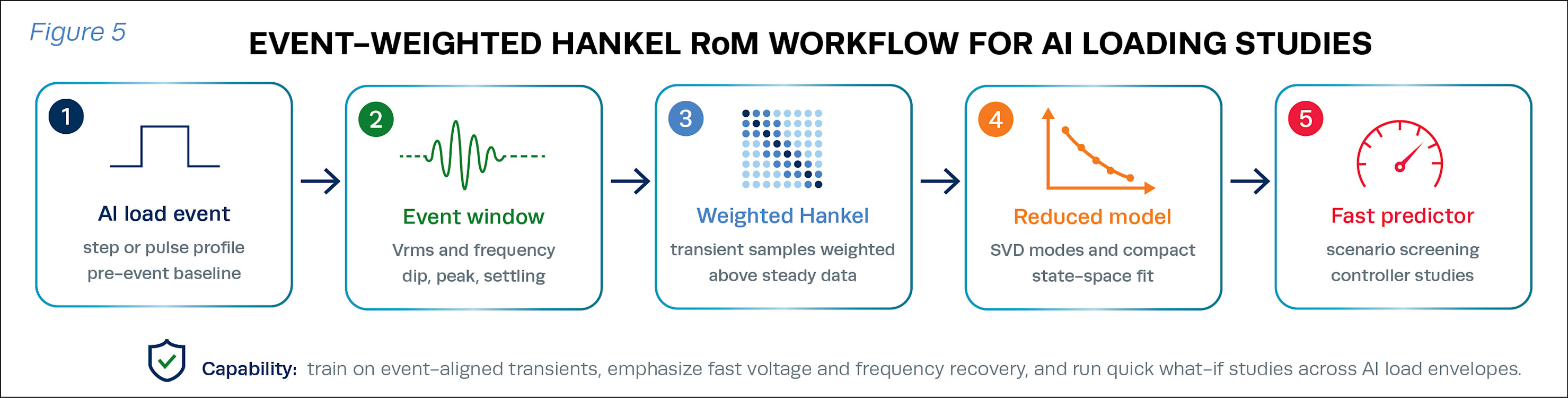
RoM can reproduce the AI loading–relevant outputs, RMS voltage and frequency, the magnitude and timing of transient dip/overshoot, and the recovery/settling characteristics, rather than internal electromagnetic states. Hankel-based reduced-order models (RoMs) are well suited to Genset modeling and sizing applications. As shown in [6], Hankel dynamic mode decomposition with control embeds voltage, frequency, and load-command histories into compact Hankel matrices, retains dominant modes via SVD, and identifies a fast state-space predictor. For a 180-kW synchronous generator, [8] reports RMS-voltage and frequency errors of 0.22 V and 0.30 Hz, respectively, with microsecond-level inference per time step.
Figure 5 illustrates the event-weighted Hankel RoM workflow, where AI load events and generator response windows are converted into a compact reduced-order predictor for fast AI loading studies.
The RoM can be trained from either a validated Simulink generator model or test-cell measurements. Simulation-based training provides safe, broad coverage of load steps, pulse sequences, power-factor cases, and AI loading envelopes. Experimental training captures real dynamics and nonidealities, including engine delay, actuator limits, AVR response, and sensor filtering. A hybrid workflow is preferred: train broadly in simulation, then refine and validate using measured events from the target genset.
REHLKO GENERATOR MODELING
Our physical modeling approach targets system-level 3-phase dynamic parameterization of an existing Genset rather than geometry redesign; therefore, time-step FEA is computationally prohibitive, and MEC/MoM introduce unnecessary geometry-modeling overhead for this use case.
We instead follow the IEEE Std 1110 synchronous-generator model family by selecting a defined d–q axis structure (Model 2.x or higher in Figure 4) and using SSFR methods consistent with IEEE Std 115 to identify the parameters required by that structure from SSFR data. Importantly, this workflow supports high-fidelity candidates such as Model 3.3, which adds rotor damper circuits on both axes and can better capture sub-transient dynamics and damping over a wider disturbance bandwidth than lower-order or single-reactance models. Because SSFR is performed at standstill, it remains practical and avoids the operational burden and risk associated with heavy time-domain short-circuit testing.
MAIN BENEFITS OF MODELING
The main benefit of this modeling approach is improved transient and small-signal fidelity by capturing damping, sub-transient behavior, and field-circuit interactions often missed by simplified models. In addition to this physical modeling approach, RoM model can also be trained and refined with test-cell measurements to capture and predict real Genset dynamics, limits, delays, and control-system non idealistic.
RoM APPROACH
RoM approach is developed for prediction, to enable faster-than-real-time studies while preserving coupled voltage–frequency behavior. Training is either from the validated simulation model and/or calibrated with measured event windows. For data center applications, an event-weighted RoM bridges detailed generator dynamics and data center-scale power stabilization analysis by enabling rapid evaluation of AI workload timing, ramp limits, GPU power smoothing, rack-level storage behavior, and generator sizing. This modeling approach is more dynamic than a lookup table, far faster than the full simulation model, and compact enough for optimization, controller-in-the-loop testing, and real-time digital-twin monitoring.
EXPERIMENTAL VALIDATION
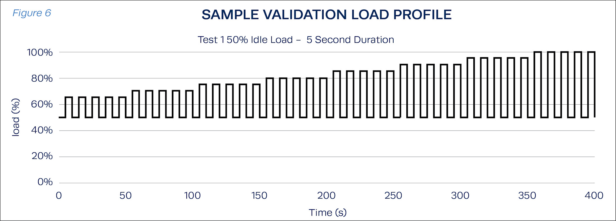
To confirm generator stability under fast-switching AI loads, the system was tested against a load profile that covers a full range of load step magnitudes and durations. The loads being applied are increased by 5% in each round, starting at 25% and increasing to 100%. The duration of the load step is varied from 1-5 seconds across runs.
To capture the full range of load steps the base load of the idle state is also varied across runs from 10-50%. In total, 900 different load steps were tested. An example of the 50% base-load case is shown in Figure 5. Although the loading profile can be faster, the profile presented In Figure 6 is based on a customer-requested AI-loading profile.
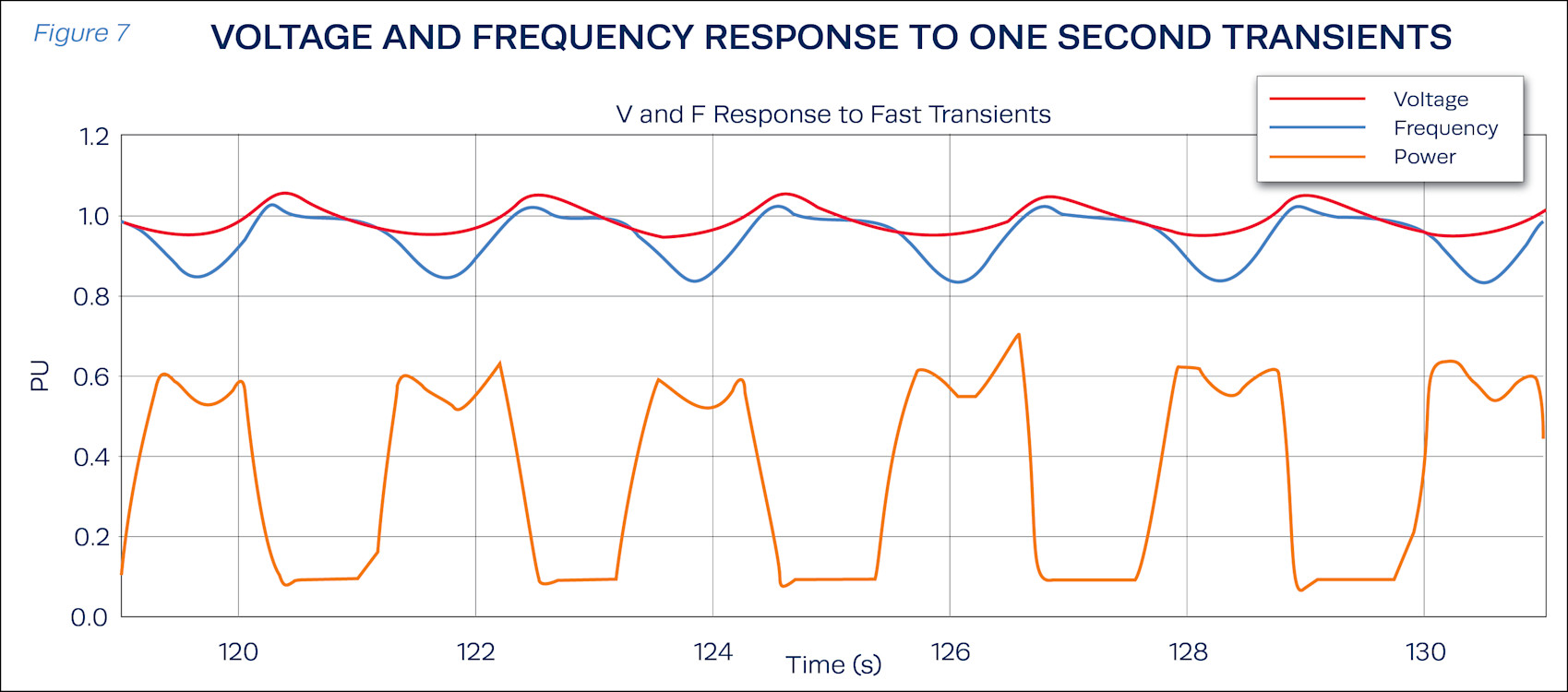
Throughout the testing the system did not go unstable. The largest risk for instability would be when significant load transients are being applied while the system is still recovering. In Figure 7, one-second transients are occurring that do not allow the system to recover to a steady state condition, yet the controller operation remains consistent and continues to react consistently and predictably.
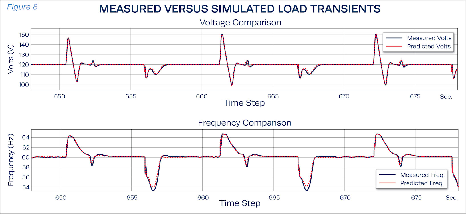
To assess performance, the Rehlko model was compared against this dataset collected from several long duration tests conducted over a period of a few hours. Overall, the model shows very strong correlation of the magnitude and duration of overshoots at load rejection and dips during load application. Across all captured conditions, an average deviation of 2% is observed in Figure 8.
With a combination of laboratory and simulation based testing Rehlko can confirm that its generators can accept the loads being presented by today’s AI data center loads. With confidence in the Simulation Models a broader range of loading scenarios can be tested to confirm constituent operation in small corner cases.
REFERENCES
[1] E. Choukse, et al. “Power stabilization for AI training datacenters.” arXiv preprint arXiv:2508.14318 (2025).
[2] NERC Issues Level 3 Alert, Reliability Guideline Focused on Large Load Challenges
[4] Building the 800 VDC Ecosystem for Efficient, Scalable AI Factories | NVIDIA Technical Blog
[6] IEEE Guide for Synchronous Generator Modeling Practices and Parameter Verification with Applications in
Power System Stability Analyses,” in IEEE Std 1110-2019 (Revision of IEEE Std 1110-2002) , vol., no., pp.1-92, 2
March 2020, doi: 10.1109/IEEESTD.2020.9020274.
[7] IEEE Guide for Test Procedures for Synchronous Machines Including Acceptance and Performance Testing
and Parameter Determination for Dynamic Analysis,” in IEEE Std 115-2019 (Revision of IEEE Std 115-2009) , vol.,
no., pp.1-246, 27 March 2020, doi: 10.1109/IEEESTD.2020.9050934.
[8] E. Sadeghi, E. Miller, K. Sado and A. Nasiri, “Data-Driven Reduced-Order Modeling and Prediction of
Synchronous Generator under Pulse Loads,” 2025 IEEE Energy Conversion Conference Congress and
Exposition (ECCE), Philadelphia, PA, USA, 2025, pp. 1-6, doi: 10.1109/ECCE58356.2025.11260354.
ABOUT THE AUTHOR
Majid Adeli is a Staff Engineer in Advanced Development, Software & Systems. He received his B.Sc. and M.Sc. degrees in Electrical Engineering from IKIU, Iran, and his Ph.D. in Electrical Engineering from the University of South Carolina.
Majid’s work focuses on power system simulation, advanced power electronics, and power converter design, with expertise in multilevel converters, inverter systems, control strategies, simulation, and hardware prototyping. Majid applies his background to the development and validation of advanced electrical systems for high-performance power applications.
ABOUT REHLKO
A global leader in energy resilience, Rehlko delivers innovative energy solutions that sustain and improve life across home energy, industrial energy systems, and powertrain technologies with control, resilience, and innovation. Leveraging the strength of its portfolio of businesses — Power Systems, Clarke Energy, Home Energy, and Engines—and its more than a century of industry leadership, Rehlko provides power where and when the grid cannot. Rehlko goes beyond function and individual recovery to create better lives, communities, and a more durable and energy-resilient future.