Managing AI Data Center Loads with Hybrid Power and Grid Forming Inverters
 Print
PrintAUTHOR
Justin Lenoff
Group Applications Manager - Microgrids
INTRODUCTION
AI-driven data centers present unique power characteristics, including large and rapid load swings that demand a hybrid power architecture. In such systems, the engine-generator serves as the muscle (delivering steady-state power), while Battery Energy Storage Systems (BESS) act as the reflexes (providing sub-second stabilization and rapid response).
Projects typically combine technologies from multiple vendors, making integration between the BESS inverter, and power systems a primary challenge. This white paper consolidates key technical insights in designing hybrid energy solutions for AI data centers.
GLOSSARY OF TERMS
Before we get started, let’s review the glossary of terms below to familiarize ourselves with AI data center, power system, and system control terminology. See Figure 1.
Term | Definition |
|---|---|
AI Load | A highly volatile electrical demand profile created by GPU- or accelerator-based computation. AI loads can exhibit synchronized power swings exceeding 50–100% of baseline levels within seconds. |
AC Bus | The primary alternating-current electrical bus to which all generating sources, inverters, and loads are connected. Voltage and frequency on the AC bus are maintained by grid-forming assets. |
BESS (Battery Energy Storage System) | A system composed of battery modules, inverters, and controls that store and discharge energy. In AI hybrid systems, the BESS provides sub-second stabilization to smooth rapid load fluctuations. |
Droop Control | A control method used by inverters and engines to share real and reactive power proportionally. Frequency and voltage “droop” settings determine how each source reacts to deviations, ensuring load sharing without oscillation. |
EMS (Energy Management System) | High-level control software that optimizes energy dispatch over extended time frames (hours to days). It manages generator scheduling, battery cycling, grid purchases, and participation in demand-response or tariff optimization programs. |
Frequency Ride-Through (FRT) | The ability of an inverter or generator to maintain connection and operation during short-term frequency deviations outside nominal limits. |
Grid-Forming Inverter | An inverter capable of establishing and maintaining a stable AC voltage and frequency reference without relying on an external grid. It provides instantaneous power balancing through sub-second droop control and reactive power support. |
Grid-Following Inverter | An inverter device that synchronizes precisely to an existing AC grid reference and cannot independently generate or form its own voltage or frequency output. This type of inverter is frequently used in grid connected solar power or energy storage applications where the external grid serves as the definitive reference point. |
LVRT / HVRT (Low / High Voltage Ride-Through) | The capability of an inverter or generator to remain online during voltage sags (LVRT) or surges (HVRT), maintaining support until conditions return to nominal. |
MBMS (Master Battery Management System) | A supervisory control layer that aggregates individual battery racks or modules into a unified system. It communicates with the PMS or inverter to coordinate energy dispatch and manage battery safety, SOC, and SOH. |
PPC (Power Plant Controller) | Real-time controller that coordinates power flow between the EMS and site assets (engines, inverters, BESS). It manages sub-second set points for real and reactive power, ensuring voltage, frequency, and power factor stability. Manages voltage, frequency, and power coordination across multiple generation assets at the plant or site level. Often integrated within inverter OEM solutions.. Sometimes referred to as a Power Management System (PMS). |
Pure Sinusoidal Waveform | The ideal AC voltage and current waveform maintained by grid-forming inverters. It represents stable, distortion-free power quality on the AC bus. |
Reactive Power (VARs) | The portion of power that supports voltage regulation in AC systems. Inverters and generators supply or absorb reactive power to maintain voltage stability. |
SCADA (Supervisory Control and Data Acquisition) | Traditional automation layer that provides monitoring, control, and data visualization for plant operations. In hybrid power systems, SCADA often interfaces with the PMS or EMS but is not optimized for dynamic AI load response. |
SOC / SOH (State of Charge / State of Health) | Metrics used to represent current energy content (SOC) and long-term battery condition (SOH). Managed by the MBMS to ensure safe and efficient operation. |
Sub-Cycle Response | The inverter’s ability to react to electrical changes within a single AC waveform cycle (<16.7 ms at 60 Hz), enabling precise correction of fast transients. |
Governor Control | Mechanical or electronic regulation of engine speed and power output. In hybrid systems, governors provide slower (hundreds of milliseconds to seconds) corrections that complement inverter-based fast controls. |
Hybrid Power Architecture | A power system combining multiple generation and storage technologies (e.g., gas engines + BESS + renewables) to achieve both steady-state power and fast transient response. |
Figure 1 - Glossary Of Key AI Data Center Terms
FOCUS AND FRAMEWORK
A central integration challenge in AI hybrid systems lies in the inverter and Power Management System (PMS) layers. An Energy Management System (EMS) is responsible for building and maintaining unit and block level dispatch schedules, typically over a 24-hour period. These schedules can be time-based, or adaptive. However, with a volatile load, the PMS and especially the inverter must maintain frequency and AC bus stability.
Because each inverter OEM employs a distinct control philosophy and often partners with preferred PMS vendors, this document provides inverter-led control guidance—assuming the inverter plays the primary role in maintaining AC bus stability.
CONTROL LAYER DEFINITIONS
INVERTER SUB-CYCLE AND SUB-SECOND POWER CONTROL
For AI applications, because the load is so volatile, a fast-responding system needs to be able to monitor the AC bus in real time and respond to frequency and voltage deviations. This is handled by the inverter (referred to here as a grid forming inverter) to ensure AC bus voltage and frequency stability during fast transients and high-rate load swings.
Overall, the inverter is responsible for ensuring that a stable, relatively pure sine wave remains constant on the AC bus. It watches for frequency changes and can either absorb energy into the battery or pull energy from the battery to ensure that frequency, voltage, and current remain stable.
ENERGY MANAGEMENT SYSTEM
An EMS coordinates dispatch and optimization over 24-hour and greater time periods. It ensures engine-generators are dispatched online or offline according to site conditions and optimizes battery operation for both State of Charge (SOC) and State of Health (SOH) targets.
A true EMS system is adaptive. It can adjust its schedules to changing source and load conditions and perform a function called “economic dispatch,” meaning that it is trying to optimize its schedules in a way that reduces total site energy costs. An EMS will dynamically balance between onsite generation, grid purchases, battery dispatch (or charge) and solar data in a way to reduce overall energy costs.
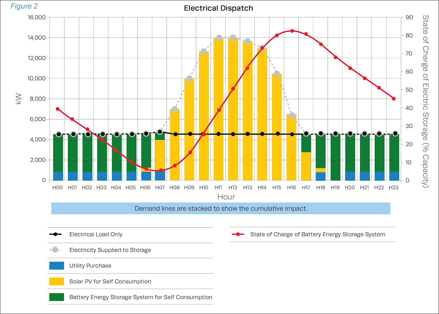
As mentioned, an EMS is responsible for coordinating dispatch over a long timeframe, typically hours or days. In Figure 2 above, the EMS is balancing grid purchase, battery State of Charge against solar production such that the battery achieves one cycle per day. An advanced EMS may also coordinate with the utility or a demand response provider (DRP) to participate in revenue generation programs or take advantage of a tariff structure to reduce grid purchase costs, especially demand charges. Note – while the chart above is not for a data center application specifically, it displays the fundamental role of an EMS.
SUPERVISORY CONTROL AND DATA ACQUISITION
A Supervisory Control and Data Acquisition (SCADA) system is traditionally responsible for controlling building operations or a manufacturing process. A SCADA system integrates a network of PLCs into a single data interface that a plant operator can view for a consolidated view of their operation. A SCADA system, in principle, can be used to control Distributed Energy Resources (DERs) like solar, generators and storage. However, a SCADA system is limited by its computation ability. It uses basic logic for mathematical computations and fixed time frames to create schedules.
Because load and source conditions can change, a SCADA’s dispatch schedules may become sub-optimal or even irrelevant, depending on site conditions. Due to the continuously changing source and loads, an EMS is a better solution for AI data centers.
POWER PLANT CONTROLLER
In data centers, the Power Plant Controller (PPC) is the Power Management System (PMS) and receives real-time set points from the EMS or customer SCADA. The PPC coordinates real and reactive power dispatch across all controllable assets under its command. It may also manage a subset of assets (e.g., Battery Energy Storage System (BESS) + inverters) or all hybrid elements (BESS, inverters, and engine-generators), depending on the customer architecture.
A PPC is responsible for coordinating volt/var set points across all assets being managed by the EMS. Think of a PPC as a set of relays that transmits signals, in near real time (sub second and millisecond) based on the “plan” that the energy management system sets.
MASTER BATTERY MANAGEMENT SYSTEM
A Master Battery Management System (MBMS) aggregates individual DC battery modules into a unified BESS system that communicates directly with the PMS or PPC. This simplifies the job of the PMS as the MBMS will be responsible for coordinating energy dispatch from individual DC blocks to fulfill volt/var points set by the PMS. The MBMS is typically coordinated by the battery supplier.
FREQUENCY AND VOLTAGE COORDINATION
In AI hybrid systems, frequency and voltage stability are jointly maintained through coordinated control between the inverter and engine governor. The inverter typically assumes the primary role in stabilizing the AC bus through fast-reacting droop control, responding to rapid load fluctuations on a sub-second timescale. Its control algorithms continuously monitor AC frequency and voltage, injecting or absorbing real and reactive power as needed to maintain a pure sinusoidal waveform.
Engines used in engine-generators, by contrast, operate on slower mechanical and governor based ramp rates, generally in the range of several hundred milliseconds to seconds. They provide the steady-state power foundation but are not designed to react to transient AI load spikes. The typical response for an engine is within the timeframe for what an EMS control system operates. Therefore, the inverter leads the control hierarchy during sub-second dynamic events, while the Power Management System (PMS) ensures that the inverter and engines remain synchronized and that overall system frequency, voltage, and power factor stay within defined tolerances. Finally, the EMS leads hour and day ahead schedules so assets are ready for dispatch when they are needed.
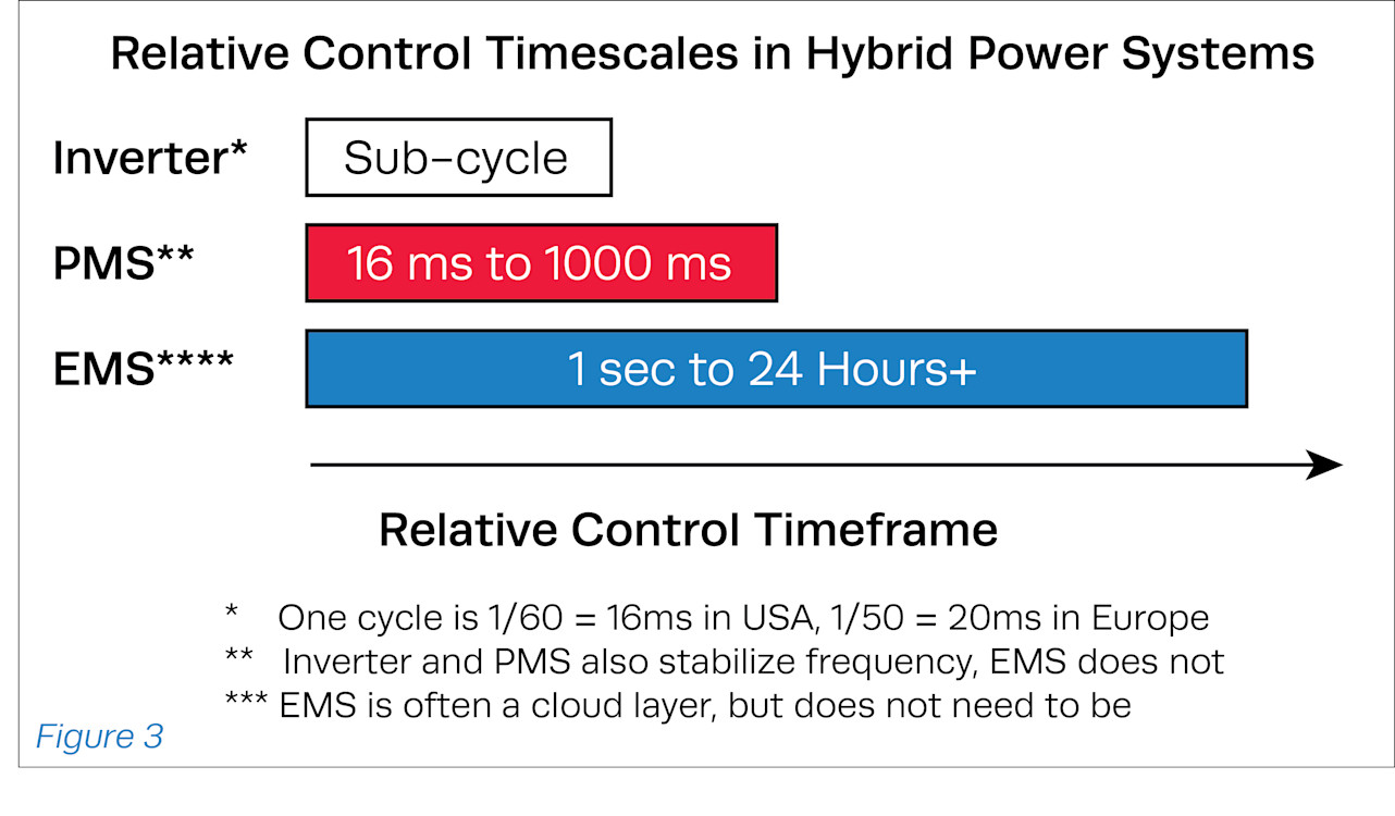
Figure 3 illustrates the relative response times of the three primary control layers in a hybrid AI power system. The inverter operates at the sub-cycle level, maintaining instantaneous voltage and frequency stability on the AC bus. The Power Management System (PMS) coordinates real and reactive power dispatch across all controllable assets within milliseconds, while the Energy Management System (EMS) performs slower, supervisory functions such as scheduling and economic dispatch over periods ranging from seconds to 24 hours or more.
Note: The Battery Management System (BMS) and Master Battery Management System (MBMS) are not shown, as they do not actively control power or energy on the AC bus. These systems operate internally within the battery stack to monitor cell health, temperature, and safety limits, communicating allowable charge and discharge parameters to the inverter or PMS. SCADA is not shown either because that is also a “coordination layer” that can sometimes act as a microgrid controller or EMS, depending on site requirements.
AI LOAD CHARACTERISTICS
When sizing a battery for an AI data center, think of the load curve as a series of rapid fluctuations around a steady average that the engines are designed to maintain. The area above the engine’s average output represents energy the battery must discharge to cover load peaks, while the area below represents energy it must absorb (charge) when the load dips. If you imagine the load curve as a graph, the battery’s job is to “fill in” the area between the load trace and the steady engine line—this area is effectively the integral of power over time, or energy (MWh).
By summing or integrating that area over one hour, you can estimate the energy exchanged by the battery in an hour, then multiply by 24 to approximate the daily throughput (MWh/day). This simple method provides a quick way to estimate how large the battery needs to be to smooth the load. In detailed design, engineers refine this by accounting for round-trip efficiency, State of Charge limits, and degradation margins, but the core idea remains the same—the battery’s energy capacity equals the area needed to flatten the load curve around the engine’s average power.
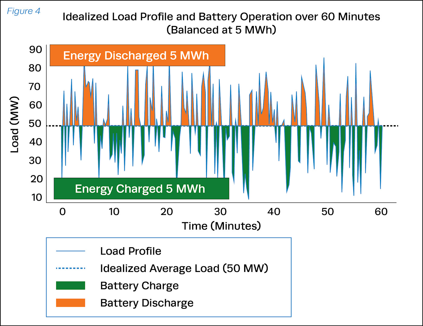
Figure 4 illustrates how a Battery Energy Storage System (BESS) mitigates rapid load swings in an AI data center. The blue trace represents the instantaneous site load, characterized by high frequency volatility typical of GPU clusters. The battery discharges (orange) during load peaks and charges (green) during troughs, maintaining an average load of approximately 50 MW on the gas engines. By performing this real-time energy balancing, the BESS absorbs short-term transients, allowing the engines and PMS to operate within optimal ramp rates while the inverter maintains AC bus frequency and voltage stability. Note, this load is idealized for the following reasons 1) The engines will run close to 80% to 85% and will perform some load following, the engines are shown as a flat dotted line here for simplicity. 2) Charge and discharge energy will not be equal due to inefficiencies and 3) There will be a base load underneath the 50 MW average that is not shown here.
Additional resource: How New GB300 NVL72 Features Provide Steady Power for AI | NVIDIA Technical Blog
ACTIVE POWER CONTROL FOR FAST RESPONSE
The power triangle (see Figure 5) illustrates the relationship between real power (kW), reactive power (kVAR), and apparent power (kVA) on the AC bus. More precisely, the power triangle represents the first quadrant of a broader four-quadrant inverter control system, where both real power and reactive power can be either supplied or absorbed. In hybrid architectures, both the gas engines and the inverters supply real power, but their control roles differ; engines provide steady-state real power, while inverters perform rapid real power adjustments and regulate reactive power to maintain voltage and frequency stability. By dynamically modulating reactive power and fine-tuning power factor, the inverter preserves AC bus quality during fast AI load swings, allowing the engines to operate efficiently at stable output levels.
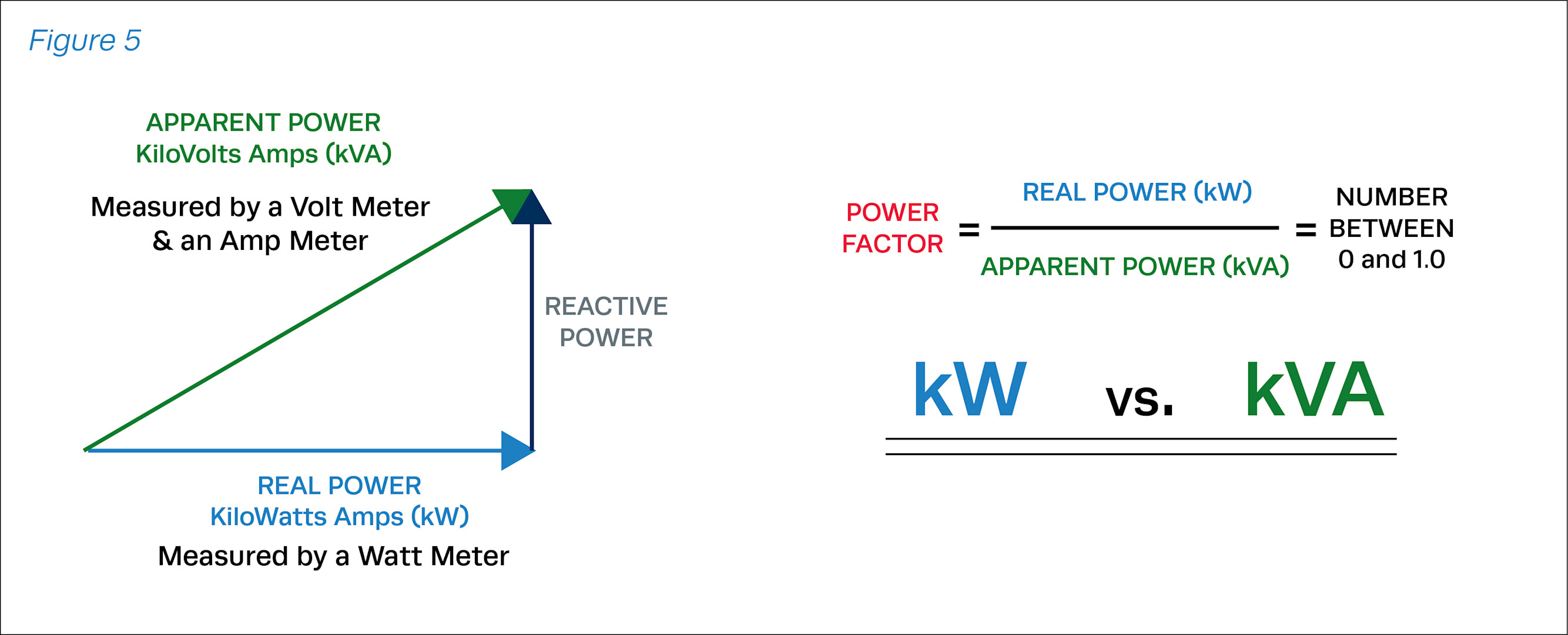
For AI data center applications, this distinction is important because fast load swings are both an energy-balancing challenge and a power-quality challenge. A four-quadrant inverter can discharge or charge real power while independently supplying or absorbing reactive power. In practical terms, the BESS inverter is not limited to simply charging or discharging the battery; it can simultaneously smooth MW fluctuations and regulate voltage through dynamic kVAR control.
During an AI load step, the inverter may need to inject real power within milliseconds while also supplying or absorbing VARs to keep bus voltage stable. During a load drop, it may need to absorb real power into the battery while continuing to provide voltage support. Because both kW and kVAR consume inverter kVA capacity, designers should ensure the inverter has sufficient apparent power headroom for simultaneous real and reactive power response.
INVERTER OEM CONTROL TOPOLOGIES
Volatile AI loads are a new and emerging problem and different inverter OEMs have different approaches to solving this problem. This document shows control topologies being utilized by the three inverter OEMs. Each topology is slightly different, but overall, many of the OEMs require direct feedback from the load into the inverter, enabling them to watch and respond quickly to any changes. See Figure 6.
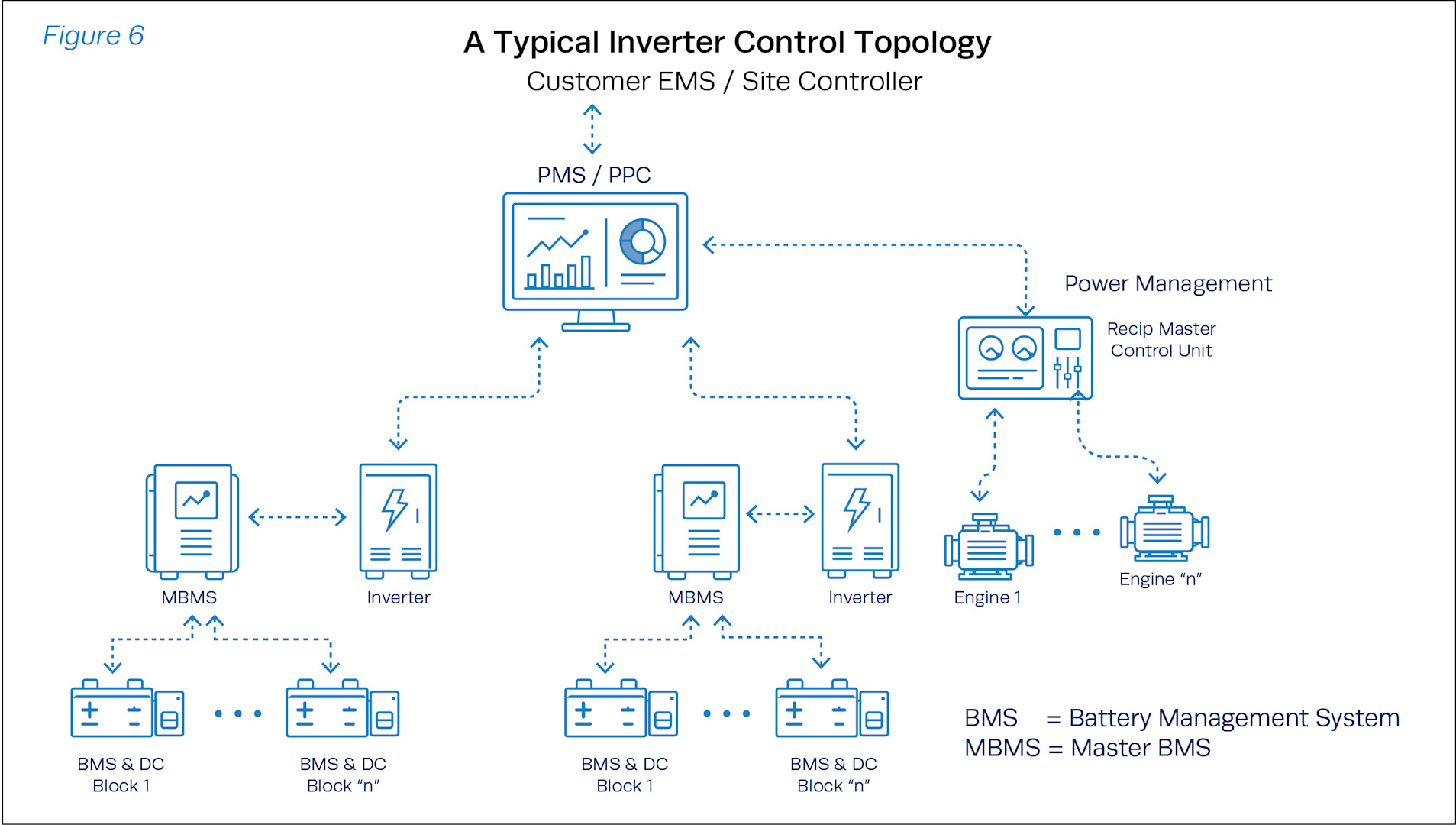
The PPC controller sits between the EMS and the centralized controllers for each individual asset or block. This means the PMS coordinates volt/var set points between the engine master controller, inverters, and any other resources available for dispatch.
SUMMARY
Hybrid power systems for AI data centers must be designed to handle highly dynamic and rapidly fluctuating electrical loads while maintaining strict voltage and frequency stability. This is achieved by pairing engine-generators, which provide efficient and reliable steady-state power, with Battery Energy Storage Systems (BESS) and grid-forming inverters that deliver fast, sub-second response to transient load changes.
System performance depends on a layered control architecture operating across distinct timescales. Grid-forming inverters stabilize the AC bus in real time by managing frequency, voltage, and reactive power. The Power Management System (PMS/PPC) coordinates real and reactive power dispatch across all assets on a millisecond basis, ensuring synchronized operation. At a higher level, the Energy Management System (EMS) optimizes dispatch, battery utilization, and economic performance over hourly to daily intervals.
Effective integration between these control layers—along with coordinated droop settings, robust communication, and clear control hierarchy—is essential to prevent instability and ensure reliable operation. Proper BESS sizing and dispatch strategies must be aligned with the unique characteristics of AI loads, where the battery continuously absorbs and supplies energy to smooth fluctuations around the engine baseline.
Successful hybrid architectures rely on precise coordination of distributed energy resources, and a holistic design approach that balances instantaneous power quality with long-term efficiency and system resilience.
ABOUT THE AUTHOR
Justin Lenoff, Group Applications Manager at Clarke Energy, is a leader in microgrid technology, energy storage systems, and engineering management, with extensive expertise in hybrid energy solutions and innovative product development. Justin specializes in the integration of Distributed Energy Resources (DERs) like Energy Storage Systems, CHP, solar, and advanced microgrid controls, including EMS and PLCs.
He is responsible for developing feasibility studies, selecting technology vendors, and structuring long-term service agreements (LTSAs) to balance stakeholder interests. He has secured significant industry achievements, including a $52M DOE grant for a long-duration solar storage microgrid in Casa Grande, AZ, and the development of over 250 MW of hybrid energy projects across the USA, UK, Australia, and Sub-Saharan Africa.
Mr. Lenoff obtained a B.S. in Electrical Engineering from New Jersey Institute of Technology and an M.S. in Engineering Management from Pennsylvania State University.
ABOUT REHLKO
A global leader in energy resilience, Rehlko delivers innovative energy solutions that sustain and improve life across home energy, industrial energy systems, and powertrain technologies with control, resilience, and innovation. Leveraging the strength of its portfolio of businesses — Power Systems, Clarke Energy, Home Energy, and Engines—and its more than a century of industry leadership, Rehlko provides power where and when the grid cannot. Rehlko goes beyond function and individual recovery to create better lives, communities, and a more durable and energy-resilient future.